As IQGeo focuses on “building better networks”TM with telecom and utility companies, we have developed four key advantages to manage the entire network lifecycle:
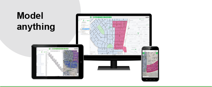
- Model anything
- Integrate everything
- Use anywhere
- Innovate constantly
In part one of our four-part series, we look at how IQGeo can help a utility or telecom operator model anything their network requires. We focus our modeling capabilities on the tenet that operators must be able to model every facet of the network in order to effectively manage it.
The network digital twin
A digital twin of the physical network transforms every asset and data point into a single geospatial model, accessible to different business units in the ways they need to see and work. Through this digital model, teams can collaborate in the planning, sales, maintenance, and development of the physical network. Operators can also gain insights into the network as its various assets operate, which can benefit alternate scenarios or future expansion as well as provide the baseline for proactive network maintenance.
1. Model any asset
IQGeo provides a comprehensive set of tools that allow the creation and extensions of a network model to provide a true representation of your physical network. This network model can be created by a telecom or utility professional using our data modeling tools without any need to write code:
- Structures and forms. These include the building and its relevant civil structure network such as cabinets, underground routes and utility boxes; poles, mid-span aerial attachment points, and wall box; and overhead and microwave routes or cellular coverage areas. The user can also easily extend this model to capture forms related to the permitting required for new trenching or attaching to existing structures, like poles or leasing new conduit capacity.
- OSP equipment. At the OSP equipment level, assets are contained within the civil structure network and related to all the civil assets in which they reside. Fiber strand splicing, equipment port to port connectivity and cabling relationships are all managed within the civil structure layer and are easily reported on and visualized by reporting mechanisms, including dynamic structure and fiber trace schematics with as-designed fiber loss calculations.
- ISP equipment. Within ISP network locations, IQGeo delivers hierarchical design modeling for every layer of the ISP environment, from floors, rooms, and suites to splice closures, riser cabling, racks and rack mounted passive ad electronic equipment, fiber distribution hubs or terminals. We do so to each suite’s ONT and gateway terminations and residential or commercial MDU’s. Optionally capturing this level of detail within an ISP location of any kind extends to the ability to manage planning, design, installation, troubleshooting and maintenance activities, all against the same asset within the digital twin.
- Cables, conduits and circuits. The conduit, cabling, and circuit layers of the network model are also contained within the civil structure network and are associated to their related civil structure and equipment objects. Cables and conduits are both configured to display their physical route paths derived from the civil structure network, relationships to one another, and their used capacities, based on cable diameter within the inner diameter of conduit and of each fiber cable based on circuit reservations on each fiber strand. The circuit layer is assigned on the fiber strand, cable segment, splice point, equipment, and equipment port structures within the network model and are easily reported on for customer lookup, route tracing, and fault analysis.
2. Model any relationship
A view of assets is helpful, but the relationships, or hierarchies, between those assets is crucial to fully plan, design, maintain, and understand the network. IQGeo gives users the ability to model equipment and structure relationships themselves though an easy-to-use configuration UI. This relationship modeling capability extends to circuit types and reservation definitions as well, as the user can define different circuit types and their possible start and end point equipment to support any network circuit reservation they may need to capture.
3. Model any property
Similar to giving the user the ability to model the relationships between structures, equipment, and circuit start and end points, the configuration UI also allows users to define their own equipment, structure, circuit, and specification attribute models. The user also has the option of defining the type of field to be added to a feature, such as photo attachments, external document links, barcode scan fields, picklists, or simple integer, Boolean or string fields.
4. Model any fiber architecture
For a true network modeling solution to best benefit the market, it should be able to model any fiber network architecture in a single environment. In the configuration UI, users can define entirely new equipment and structure types, their behaviors in the network model, their attribute models, and their relationships to the structure and equipment layers. Then they can insert them into the network model and make them usable by design and planning engineers in the office or field without the need for product enhancement or customization. Whether the network being modeled is PON, XGS PON, Active-Ethernet, distributed or home run split, fiber to the node (HFC), fronthaul and backhaul cellular, converged FTTH/small cell, or utility smart grid networks, IQGeo can support the architecture.
5. Simplify the UI
Finally, the increasing complexity of telecom and utility networks demands that more members of an organization can capture various attributes and do so quickly. Traditionally, a small number of specially trained GIS experts have managed this part of the data entry process, but a simplified UI enables better cross-team access and usability. With a map view that’s increasingly familiar to smart device users as well as easy-to-use palettes and configurable assembly and “favorite” object templates, your UI can democratize modeling across your organization. It also allows field users to view and then update the model in real-time.
With these unmatched capabilities, for users across the organization, IQGeo’s approach enables telecom and utilities to model any network requirement, for existing assets and future ones. As networks grow increasingly complex and demand sudden updates, the ability to model any requirement will be essential to manage the networks of the future.

 Previous